This document outlines the documentation requirements for modelling & registering an integral heat pump water heater (HPWH) system for incentives in Australia.
| Phase | Documents |
| AS/NZS 4234 modelling | AS/NZS 5125.1 Report & Test Data (COP) AS/NZS 4692.1 Test Report (standing heat loss) Technical Details Sheet (download template here) Tank Drawing Schematic & bill of materials |
| Submission to Federal & State incentive schemes (SRES, VEU, ESS) | AS/NZS 2712 Certificate Manufacturer’s installation instructions Data Plate Images (photo or PDF) Manufacturer Declarations Authorisation Letter (if applicable) EESS registration & Electrical certificate of conformity |
Overview
Documentation that we need to submit an application to an Australian incentive scheme can be grouped into the following categories:
- Testing – electrical safety, water safety, design & construction, energy efficiency
- Certification – AS/NZS 2712, AS 3498, Electrical Safety
- Technical Details – drawings, schematics, specifications, manual, data plates, declarations
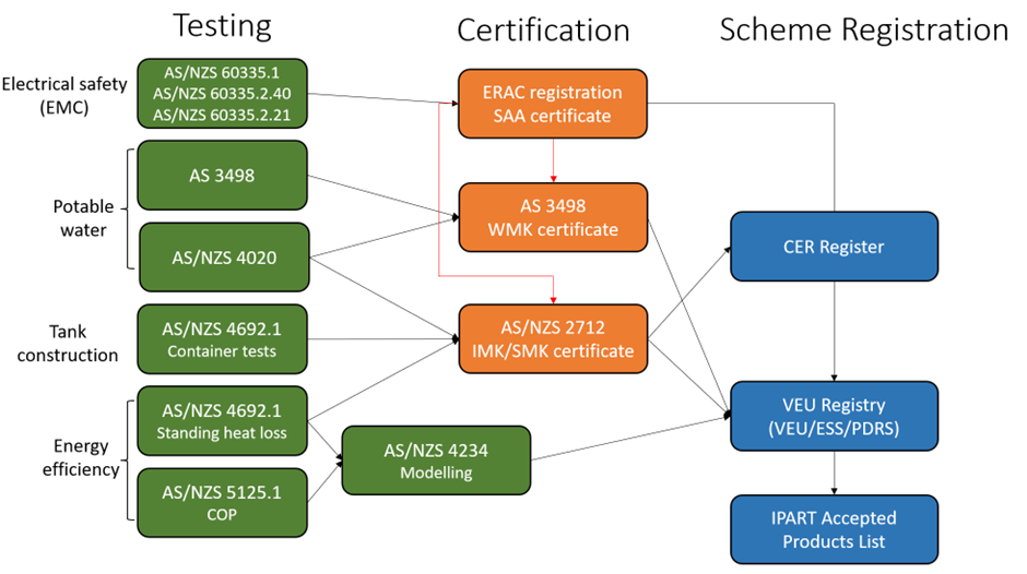
The flow chart below provides an overview of the testing & certification process:
Conformity Assessment Bodies (CABs)
Certification to the relevant standards is provided by Conformity Assessment Bodies (CABs) who are JAS-ANZ Accredited. Contact details for relevant laboratories and certification bodies can be found in the Contacts section below.
EnergyAE recommends the following CABs for HPWH certification:
Testing
We recommend to discuss precise testing requirements with your CAB early in the project.
Below are the two energy efficiency test reports that EnergyAE requires to conduct AS/NZS 4234 modelling:
AS/NZS 5125.1 Report and Test Data
AS/NZS 5125.1 measures the COP and Power draw for HPWHs across a range of ambient test conditions. These are used to create regression functions that are used in the AS/NZS 4234 annual performance modelling.
Testing can be conducted by any NATA accredited (or equivalent) laboratory, such as Intertek, CVC, SGS, VIPAC, Yukawa.
Request 1-minute test data for test condition 2 and test condition 5 (low temperature test data) from the test lab.
AS/NZS 4692.1 Test Report
AS/NZS 4692.1 measures the standing heat loss for thermal storage tanks. Testing can be conducted by any NATA accredited (or equivalent) laboratory, such as Intertek, CVC, SGS, VIPAC, Yukawa.
Certification
Three forms of product certification are required to show compliance:
- Electrical Safety Certificate of Conformity
- AS/NZS 2712 – Design & Construction
- AS 3498 – Water Safety
Products must appear on these certificate schedules in the brand & model name of the company who will later claim incentives.
Electrical Safety Certification
Electrical Safety Certification and RCM registration use the same system, called the Electrical Equipment Safety System (EESS).
Manufacturers must use electrical safety test reports[1] to apply for a Electrical Safety Certificate of Conformity[2] for installation in Australia, otherwise known as an SAA Certificate, then register the product on the EESS. Electrical Safety Certification must be provided by a JAS-ANZ accredited body, such as SAA Approvals or SGS Australia.
Australian importers must use the EMC test reports[3] and SAA Certificate to apply for Regulatory Compliance Mark (RCM) on the ERAC Database.
AS/NZS 2712 & AS 3498 Certificate
AS/NZS 2712 specifies the performance-based design and construction required for HPWHs.
AS 3498:2020 specifies the safety and public health requirements for HPWHs, including legionella control methods.
Certification must be provided by a JAS-ANZ accredited body, such as IAPMO on Intertek SAI Global.
Model Identification
These certificates may specify product model ID as well as tank model ID. It is extremely important the system, heat pump, and tank model ID are consistent between certificates, test reports and other technical details.
For all-in-one units, the system model ID should be identical to the HP and tank model ID, as there is only one data plate for the system. This model ID should be consistent across all documentation. Where the model name is not consistent in test reports or drawings, a manufacturer declaration is required.
For split systems, it is possible that there are different model names for the HP, tank, and system. This must be handled carefully to ensure consistency.
Overall:
- System model ID: the overall name of the system that will appear on certificate registers
- Heat pump model ID: the name of the HP unit as per the dataplate, AS/NZS 5125.1, 4692.1 test reports. For integral systems, this should be the same as system & tank model ID.
- Tank model ID: the name of the tank as per the tank data plate, tank drawing, AS/NZS 5125.1, 4692.1 test reports.
- Technical Details
Technical Details Sheet (TDS)
Technical details of each model must be provided for modelling & applications.
Please download the template, fill out the relevant details, and send back to EnergyAE.
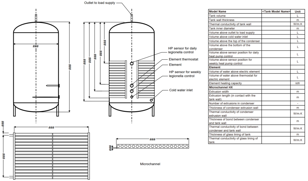
Tank and Condenser Diagram
Tank diagrams must be clearly labelled in English.
The drawing must state the Brand and Model name consistent with the AS/NZS 2712 certificate of the company applying, as opposed to the original manufacturer brand/model name.
Drawings should specify the positions of the following ports & sensors:
- Cold water inlet
- Hot water outlet (to load)
- Top & bottom of condenser (coil/microchannel)
- Heat pump temperature sensors (e.g. daily HP control, weekly legionella control)
- Element & thermostat (if applicable)
Drawings should be dimensioned with at minimum the following measurements:
- Tank inner diameter
- Tank wall thickness
- Condenser dimensions
- Wrap-around coil: tube length, inner diameter, thickness, material
- Microchannel: strip length, number of strips, internal cross section
- Port & sensor heights, and total tank height, from base of tank
It is recommended to include a tank data table in the tank drawing to ensure all tank positions are included. Please refer to Appendix A for example tank data tables and tank drawing.
Installation Manual
The installation manual must include the following information:
- Brand and Model names
- Plumbing schematic, showing piping and control valves
- Warranty Details
- The whole product (tank, compressor and parts) must be covered for at least 5 years from the date of installation. This warranty period does not extend to labour or ancillary components/parts used as part of the installation of the product.
- Must contain the following wording: “Our goods come with guarantees that cannot be excluded under the Australian Consumer Law. You are entitled to a replacement or refund for a major failure and compensation for any other reasonably foreseeable loss or damage. You are also entitled to have the goods repaired or replaced if the goods fail to be of acceptable quality and the failure does not amount to a major failure.”
- Must include contact details of who to contact regarding product warranty obligations in Australia
The manual must be consistent with the AS/NZS 4234 modelling and any other documents submitted to applications, particularly control settings and legionella control.
Control Logic Information
So that AS/NZS 4234 modelling matches real product performance, please provide the following information regarding control strategy for each model:
- What is the name of the default setting?
- What is the desired heat pump and element set point and dead-band?
- Can users permanently change control settings?
- If a user changes to a different mode, will it automatically revert to the default mode within 24 hours?
Authorisation Letter
If models are purchased from a different manufacturer and the test reports reference the manufacturer of the purchased models and their equivalent models, a letter of consent from the original manufacturer must be provided, authorizing the use of their test reports.
An authorisation letter template can be found in Appendix B.
Manufacturer Declarations
This is required if any model names differ from test reports or if testing was conducted on a prototype unit. EnergyAE will prepare this and send it for you to sign.
If a client has a AS/NZS 4692.1 or AS/NZS 5125.1 test report with a different model name as on their AS/NZS 2712 certificate, they require a declaration to show the model names are identical.
Contacts
| Intertek SAI Global | |
| Services: | AS/NZS 4692 testing AS/NZS 5125 testing AS/NZS 2712 certification AS 3498 certification |
| Contact: | Felix Li Felix.Li@intertek.com |
| Website: | https://www.intertek.com/ |
| IAPMO | |
| Services: | AS/NZS 2712 certification AS 3498 certification |
| Contact: | Adam Wegmann Adam.wegmann@iapmo.org |
| Website: | 1800 417 711 |
| CVC | |
| Services: | AS/NZS 4692 testing AS/NZS 5125 testing |
| Contact: | Tao Yucheng taoyc@cvc.org.cn |
| Website: | https://www.cvc.org.cn/ |
| VIPAC | |
| Services: | AS/NZS 4692 testing AS/NZS 5125 testing |
| Contact: | Marcus Klein marcusk@vipac.com.au |
| Website: | https://www.vipac.com.au/ |
| SGS | |
| Services: | AS/NZS 4692 testing AS/NZS 5125 testing Electrical Safety Certificate |
| Website: | https://www.sgs.com/en-au |
| SAA Approvals | |
| Services: | Electrical Safety Certificate |
| Website: | https://www.saaapprovals.com.au/ |
| Yukawa | |
| Services: | AS/NZS 4692 testing AS/NZS 5125 testing |
| Contact: | Satya Mavuri contact@yukawalab.com.au |
| Website: | https://www.yukawalab.com.au/ |
Tank drawing requirements
| Model Name | [Tank Model Name] | Unit |
| Tank volume | L | |
| Tank wall thickness | m | |
| Thermal conductivity of tank wall | W/m.K | |
| Tank inner diameter | m | |
| Volume above outlet to load supply | L | |
| Volume above cold water inlet | L | |
| Volume above the top of the condenser | L | |
| Volume above the bottom of the condenser | L | |
| Volume above sensor position for daily heat pump control | L | |
| Volume above sensor position for weekly heat pump control | L | |
| Element | ||
| Volume of water above electric element | L | |
| Volume of water above thermostat for electric element | L | |
| Element heating capacity | kW | |
| Glass Lining | ||
| Thickness of glass lining of tank | m | |
| Thermal conductivity of glass lining of tank | W/m.K |
| Microchannel Condenser | ||
| Extrusion width | m | |
| Extrusion length (in contact with the tank wall) | m | |
| Number of extrusions in condenser | – | |
| Thickness of condenser extrusion wall | m | |
| Thermal conductivity of condenser extrusion wall | W/m.K | |
| Thickness of bond between condenser and tank wall | m | |
| Thermal conductivity of bond between condenser and tank wall | W/m.K |
| Wrap Around Coil | ||
| Inner diameter of coil tubing | m | |
| Coil tubing wall thickness | m | |
| Total length of the coil | m | |
| Bond thickness between tank wall and coil | m | |
| Bond conductivity | W/m.K | |
| Condenser tube wall material | – | |
| Thermal conductivity of condenser tube wall material | W/m.K |