
Understanding AS/NZS 5125.1 Amendment 1 Appendix H for MEPS Testing
Standards Australia has published AS/NZS 5125.1:2014 Amd 1, which introduces Appendix H, a new laboratory test method for air source heat pump water heaters. Appendix H is the method expected to underpin minimum energy performance standards (MEPS) for heat pump water heaters under the Greenhouse and Energy Minimum Standards (GEMS) framework.
This guide explains how the Appendix H test procedure works: what it measures, the three ambient conditions it runs under, and how a tank behaves through the 24-hour test cycle. For the regulatory background and what manufacturers should do about it, see our news coverage of the amendment’s publication and the lead-up to MEPS. For a pre-assessment of your own product against this method, see our MEPS Simulation service.
Appendix H is an addition, not a replacement
Appendix H is published as Amendment 1 to the existing AS/NZS 5125.1:2014 standard, which is easy to misread as a change to the test manufacturers already know. It is not. The existing AS/NZS 5125.1:2014 test, full heat-up cycles across a matrix of ambient and water conditions, still runs exactly as before, and it still produces the COP and power input correlations that feed into AS/NZS 4234 TRNSYS modelling for STC, VEEC, and ESC registration. See Understanding Standards: AS/NZS 5125.1 for how that test works.
Appendix H is a separate, additional test procedure within the same amended standard, run under different fixed conditions for a different purpose: producing the COP that GEMS is expected to use for MEPS. Once MEPS is active, manufacturers will need both tests on the same product: the base AS/NZS 5125.1:2014 test to register for incentive schemes, and Appendix H to demonstrate MEPS compliance. Neither test result can substitute for the other.
What the test measures
Appendix H measures coefficient of performance (COP), maximum deliverable heated water volume, reheat time, recharge rate, and energy consumption. COP is the primary regulatory output: once GEMS requirements are confirmed, the MEPS pass or fail will be set against the Appendix H COP. Deliverable volume, reheat time, and recharge rate are expected to be published on the GEMS registry as informative values, so consumers and specifiers can compare products beyond a single efficiency number.
The test is run at three ambient conditions, each in a climate-controlled chamber:
| Condition | Dry bulb | Wet bulb | Dew point |
|---|---|---|---|
| Hot | 19.0°C | 13.4°C | 9.4°C |
| Average | 9.0°C | 8.0°C | 7.1°C |
| Cold | 1.0°C | 0.0°C | −1.1°C |
Every result Appendix H reports, COP, deliverable volume, reheat time, and recharge rate, is produced separately for each condition. A unit’s performance in the Cold condition is typically well below the Hot condition, since lower air temperature reduces heat pump efficiency and brings in any frosting penalty near the evaporator.
The 50°C delivery threshold
The detail that catches manufacturers out is the minimum delivery temperature used in the test. Appendix H requires delivered hot water to remain at or above 50°C for the duration of a draw. AS/NZS 4234 simulation, by contrast, uses a 45°C minimum useful delivery temperature.
That 5°C difference matters. A product with a lower set point, a narrow deadband, or a smaller storage volume, tuned around the 45°C AS/NZS 4234 threshold, can show reduced deliverable volume and a different COP once tested against the 50°C Appendix H floor. Manufacturers should review tank set point, compressor restart logic, deadband settings, boost element behaviour, and recovery strategy after a large draw-off before booking a laboratory test.
If control settings are changed to suit Appendix H, the same control logic needs to carry through to CER, VEU, and ESS scheme submissions. A product should not be tested for MEPS using one control configuration while being modelled or registered for incentive schemes under a different one.
How the 24-hour test cycle runs
Each Appendix H test cycle draws hot water from the tank in a defined sequence, then tracks how the unit recovers. The chart below shows the test-chamber conditions, average tank temperature, cold-water inlet, heated water outlet, water flow, and electrical power over a full test sequence, for a representative ~320 L integral R290 microchannel heat pump water heater modelled by EnergyAE. Test stages are marked on each chart.
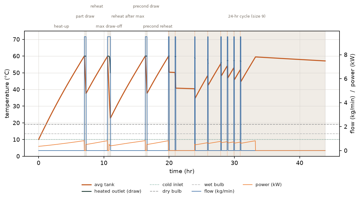 Hot condition (19°C): test-chamber conditions, average tank temperature, cold-water inlet, heated water outlet, water flow and electrical power over the full test sequence, with test stages marked.
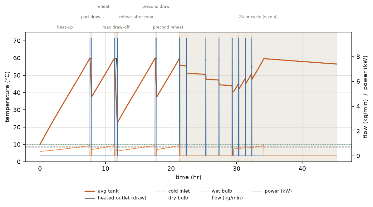 Average condition (9°C): the same variables, recorded through a full test sequence at the Average ambient condition.
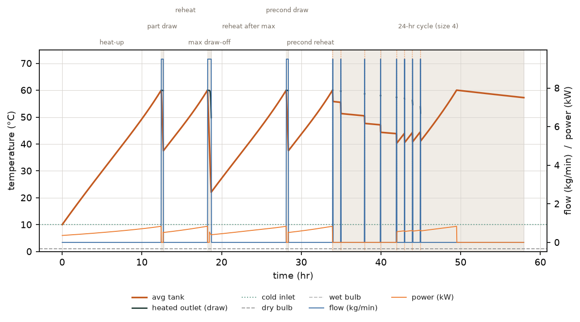 Cold condition (1°C): the same variables at the Cold ambient condition. Recovery after the largest draw-off takes visibly longer than in the Hot or Average conditions.
The load draw-off pattern and standby periods are fixed by the standard so that every tested product, regardless of manufacturer, is exercised the same way. What varies between products is how the tank and heat pump respond: how far the average tank temperature falls after a draw, how quickly the compressor restarts, and how long recovery takes before the next scheduled draw.
Tank stratification through the test
A storage tank does not heat or cool as a single uniform mass. Appendix H test data (and the models EnergyAE builds to predict it) track temperature at multiple heights through the tank, because stratification, the layering of hot water above cold, is what determines how much usable hot water is actually available at the outlet before delivery temperature drops below the 50°C floor.
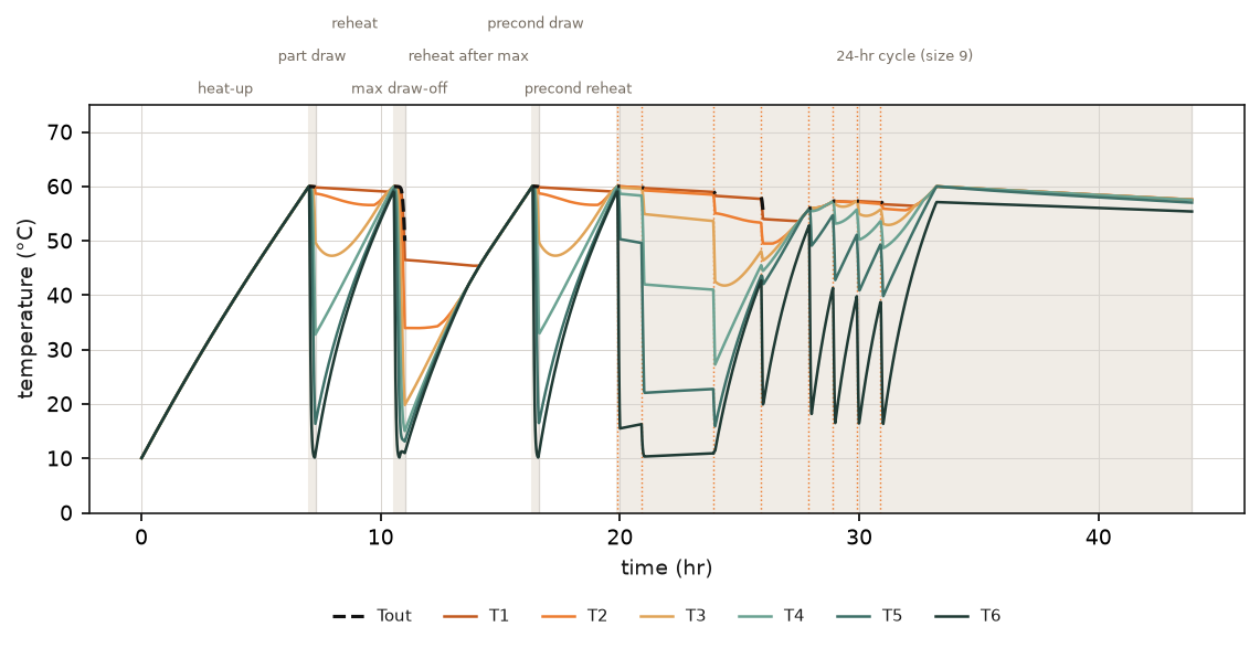 Hot condition (19°C): water temperatures at the centroids of six equally-spaced tank segments, T1 (top) to T6 (bottom), with the delivered outlet temperature Tout, over the full test sequence.
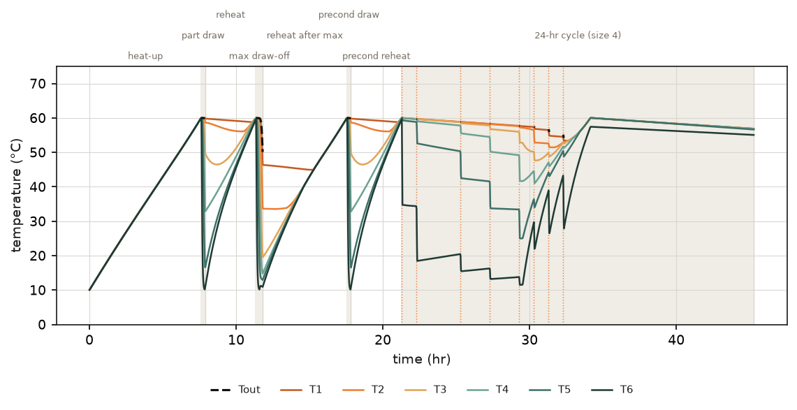 Average condition (9°C): the same six-segment stratification profile at the Average ambient condition.
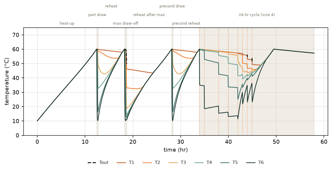 Cold condition (1°C): the same profile at the Cold ambient condition. The lower segments recover more slowly, which is the main driver of the longer recharge time seen at this condition.
A sharp, well-maintained boundary between the hot upper layers and the cooler lower layers means more of the tank’s stored volume is delivered above 50°C before the outlet temperature falls away. A tank that mixes readily, through high inlet velocity, a short aspect ratio, or a poorly placed heat pump return, delivers less usable volume for the same nominal storage size.
What the results look like
For the same representative unit, the headline deliverables Appendix H reports are:
| Deliverable | Hot | Average | Cold |
|---|---|---|---|
| Max delivery V50 (L) | 316.4 | 317.7 | 317.9 |
| Max delivery V_del (L) | 260.3 | 261.3 | 261.3 |
| Recharge time (min) | 317.7 | 344.0 | 565.3 |
| Rated 24-hr load size | 9 | 4 | 4 |
| 24-hr cycle COP | 3.65 | 3.03 | 1.95 |
The 24-hr cycle COP falls from 3.65 in the Hot condition to 1.95 in the Cold condition, a 46% reduction, driven by lower heat pump efficiency and any frosting penalty at low air temperature. Recharge time after the largest draw-off rises from roughly 5.3 hours in the Hot condition to over 9 hours in the Cold condition, and the rated 24-hour load size the unit can support falls from 9 to 4. These figures are simulated predictions for a representative product, not a declared result for any specific model, and should always be confirmed by accredited laboratory testing before use in a compliance or marketing claim.
Comparing Appendix H to AS/NZS 5125.1:2014 and AS/NZS 4234
Three distinct procedures are now in play for a single product, and it helps to be clear on what each one is for:
| Aspect | AS/NZS 5125.1:2014 (base test) | AS/NZS 5125.1:2014 Amd 1 Appendix H | AS/NZS 4234 |
|---|---|---|---|
| What it is | Laboratory test | Laboratory test | Computer simulation |
| Test conditions | Full heat-up cycles across a matrix of ambient and water temperatures, plus a low-temperature frosting test | Fixed Hot, Average, and Cold 24-hour tapping cycles | Not a lab test: consumes the base 5125.1 correlations in an annual TRNSYS run |
| Minimum delivery temperature | Not applicable (measures capacity, power, COP directly) | 50°C | 45°C |
| Primary output | COP and power input correlations by ambient and water temperature | 24-hr cycle COP, plus deliverable volume, reheat time, and recharge rate | Annual energy savings |
| What it drives | Feeds the regression model used in AS/NZS 4234 modelling | GEMS MEPS pass or fail (once confirmed) | STC, VEEC, and ESC certificate yield |
The base AS/NZS 5125.1:2014 test and AS/NZS 4234 simulation are the pathway manufacturers already use for incentive scheme registration: see Understanding Standards: AS/NZS 5125.1 and Understanding Standards: AS/NZS 4234 for how that pathway works. Appendix H sits alongside it as a separate requirement for MEPS, with its own 50°C delivery floor and its own fixed test conditions. A control setting tuned for one can cost performance under another, so all three should be modelled together to keep scheme declarations and MEPS test configuration consistent.
How EnergyAE can help
EnergyAE supports heat pump water heater manufacturers with AS/NZS 4234 modelling, incentive scheme registrations, and preparation for the upcoming GEMS MEPS framework. Our MEPS Simulation service runs the Appendix H test sequence on a validated model of your product before you book a laboratory, so you can see the predicted COP, deliverable volume, and recharge behaviour, and correct a likely fail before it costs you a laboratory slot.
Contact us to discuss AS/NZS 5125.1 Appendix H testing and MEPS preparation for your product range.