
29 September 2026 — Alastair McDowell
R290 or CO2 for a commercial hot water system
This article is a summary of the session EnergyAE presented to CEPNZ (Carbon & Energy Professionals, NZ) on 28 September 2026. The full slideshow is embedded at the end, and the slides through the article are live: the controls work - have a go.
The question it set out to answer is narrow and practical: for a commercial hot water plant, do you specify a transcritical CO2 machine or a subcritical R290 one? Both are natural refrigerants, both are being installed in Australia and New Zealand now, and the marketing for each will tell you it is the more efficient choice. But what application-specific features dictate the choice of equipment?
The answer that came out of the modelling & analysis is that the deciding factor is the distribution system, in particular, the ratio of ring-main loss to thermal load delivery. For a low loss-to-load ratio, CO2 comes out on top, for a higher loss-to-load ratio, R290 is favoured. Read on to understand the rationale.
Heat pump water heater fundamentals
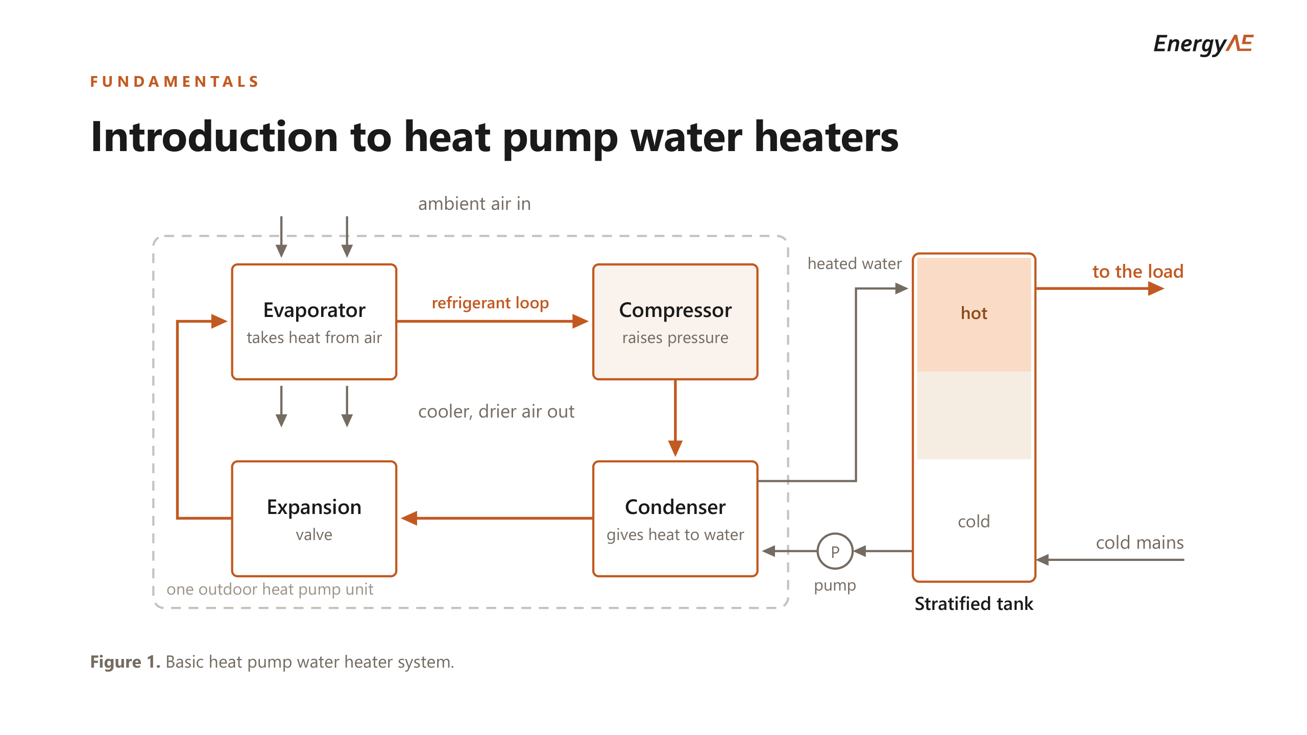
Starting with some fundamentals. A heat pump water heater moves heat from the air into water rather than making heat from electricity. Ambient air passes over an evaporator, a compressor raises the refrigerant pressure, a condenser or gas cooler gives that heat to the water, and an expansion valve drops the pressure again.
The water side matters as much as the refrigerant side. Water is drawn from the bottom of a tank, heated, and returned to the top, so the tank holds a temperature gradient with hot sitting on cold. A sensor part way up starts the machine when the water around it falls and stops it when the tank recovers.
The simulation below runs that system. Open the tap and watch the tank temperature fall, the sensor drop below its start point, and the heat pump come on. The speed control runs the clock up to 600 times real time, so a morning’s draw takes a few seconds.
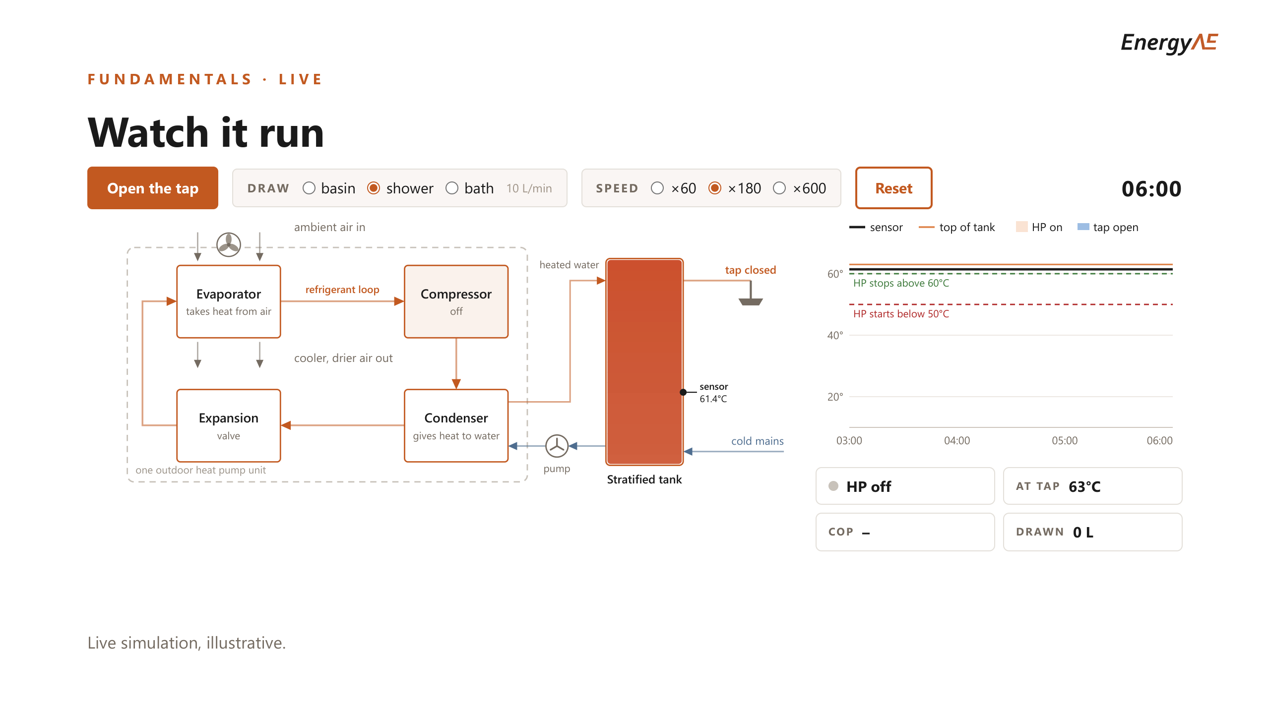
Two things in there drive the rest of the article. The COP is not a fixed number: it moves with the air temperature and with the temperature of the water arriving at the machine. And the element that tops the tank up when the heat pump cannot hold temperature runs at a COP of 1, so every kilowatt hour it contributes costs about three times what the heat pump would have charged, given heat pumps typically operate with a COP of around 3.
The two refrigerants
Three natural refrigerants are common in commercial water heating. Each has a low global warming potential and a good upper water temperature of 75 to 90°C, but each carries a safety property that requires some work-around.
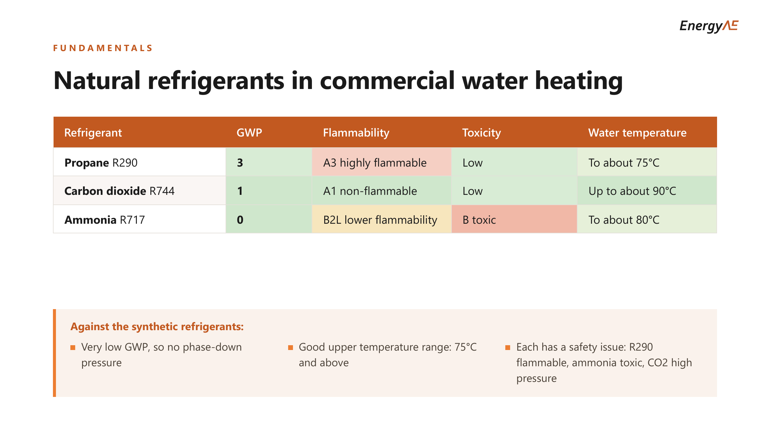
R290 is propane. It has a GWP of 3 and reaches about 75°C on the water side, and it is A3 highly flammable, which sets charge limits and generally puts the plant outdoors or in a ventilated enclosure.
CO2 is R744, with a GWP of 1. It is non-flammable and non-toxic, and it will produce water up to about 90°C without difficulty. Its constraint is that the components work under high-pressure, which makes servicing a specialist job, and the equipment is higher priced.
Ammonia appears here for completeness. It is efficient and its GWP is zero, but it is toxic, which keeps it out of most buildings where people are.
On equipment cost R290 is usually the cheaper machine to buy and the easier one to service.
Why a transcritical (CO2) machine needs cold water
The two machines run different thermodynamic cycles, and that is what drives everything below.
A CO2 machine runs transcritical. It rejects heat through a gas cooler rather than a condenser, so there is no condensing plateau and no fixed rejection temperature. Its efficiency comes instead from a wide temperature glide: it takes water in cold, lifts it a long way in a single pass, and sends it out hot. 65-75 degrees is a typical set point for CO2 systems as the target outlet temperature.
That only works efficiently if the water arriving is cold. Warm the inlet and the glide narrows and the efficiency falls with it. CO2 systems have an upper limit on entering water temperature, and systems turn off anywhere between 35-55 degrees, a setting determined at commissioning. At that point, back-up resistive elements take over.
An R290 machine runs subcritical and multi-pass. It draws from a mixed store, lifts the water a few kelvin, and returns it, over and over, until the store comes up to temperature. It is working near the top of its curve the whole time, which is the least efficient part of it, but it was already there and warm inlet water costs it very little.
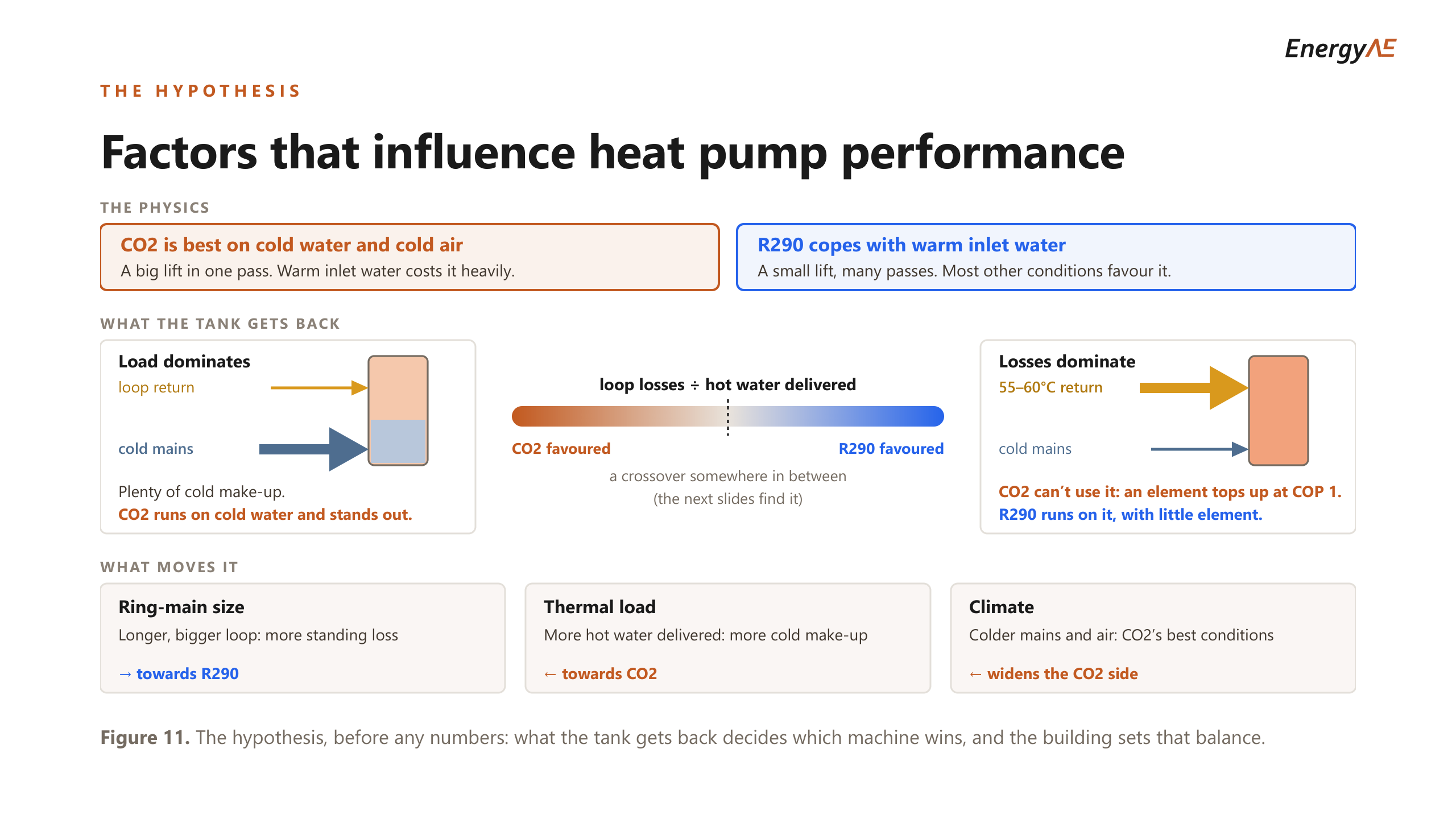
So the question is what temperature water the tank hands back to the machine. A building with a large draw and no circulating loop replaces every litre with cold mains, which is exactly the condition CO2 is built for. A building whose loop losses dominate hands back water at 55 to 60°C, which CO2 cannot use at all.
Performance testing data
Both machines were tested to EN 14511, and putting the two maps side by side shows something more useful than either curve on its own. The curves below are representative of each architecture rather than either manufacturer’s results, adjusted so that this does not publish a client’s test report.
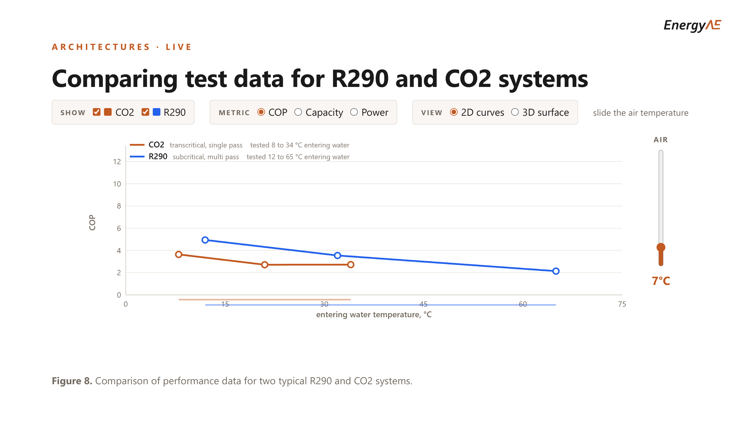
When someone asks which refrigerant is more efficient, the first question back has to be: at what entering water temperature? At 15°C the R290 machine looks superb. The catch is that on a ring main it never gets to sit there.
For this reason, it’s hard to compare CO2 and R290 based on test data alone, because both see very different ranges of entering water temperature: CO2 sees 5-30 degrees, while R290 sees 50-70 degrees. Also, CO2 lifts its outlet water directly to its target outlet, whereas R290 cycles in 5-10 K increments. Hence, it’s best to compare the two based on seasonal performance using seasonal COP or annual energy modelling, which take into account the different ways the systems operate.
Dead legs and ring main architectures
A commercial hot water system distributes in one of two ways, and the choice changes the plant more than the refrigerant does.
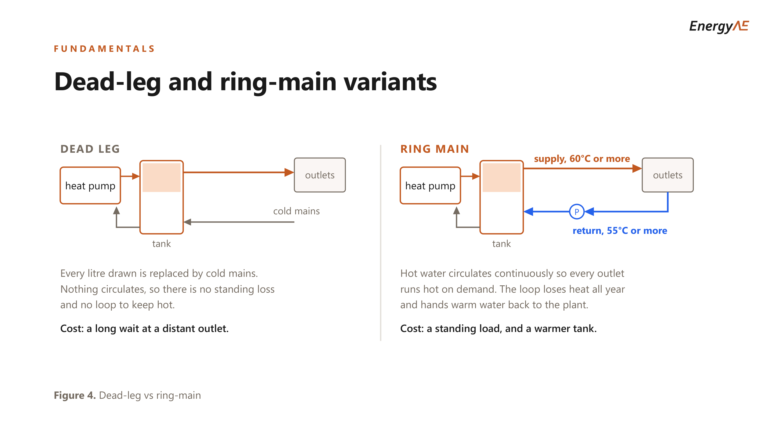
A dead leg is the simple case. Nothing circulates, so there is no standing loss and no loop to keep hot, and every litre drawn is replaced by cold mains. The cost is a long wait for hot water at a distant outlet.
A ring main circulates hot water continuously so every outlet runs hot on demand. The loop loses heat all year and hands warm water back to the plant, so the cost is a standing thermal load and a warmer tank.
AS/NZS 3500.4:2025 Clause 10.2 sets the temperatures. Water leaving a heater, bank of heaters or storage vessel must be not less than 60°C, and water returning to it must be not less than 55°C. Clause 10.6.1.2 then requires the circulating pump to be sized for a circuit temperature drop of not more than 5 K, which is the same 5 K gap seen from the other end.
That 55°C return is the coupling. It is a requirement about the distribution system, and it lands squarely on the plant, because it fixes the temperature of the water the heat pump is asked to work on.
Distribution is one of a handful of choices a commercial job makes. The others are how many heat pumps and tanks there are, whether the tanks sit in parallel at one temperature or in series so the store keeps a cold end, whether the heat pump water and the stored water are the same water or separated by a coil, whether the machine lifts the water in one pass or many, and what the pump is told to hold.
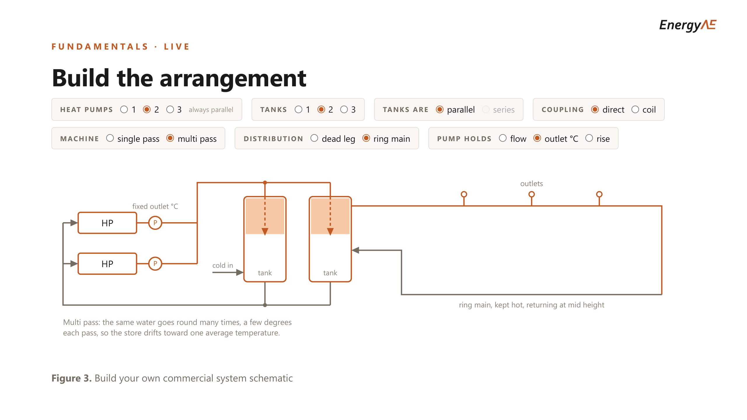
Two of those choices carry most of the weight in what follows: single pass against multi pass, and tanks in series against tanks in parallel. A single-pass machine takes water in cold and sends it out hot in one go, which needs a store with a genuinely cold bottom to draw from. A multi-pass machine lifts the same water a few kelvin at a time, so its store drifts toward one average temperature.
System architectures
Given a ring main, each machine forces a different arrangement, and neither designer gets a choice about it.
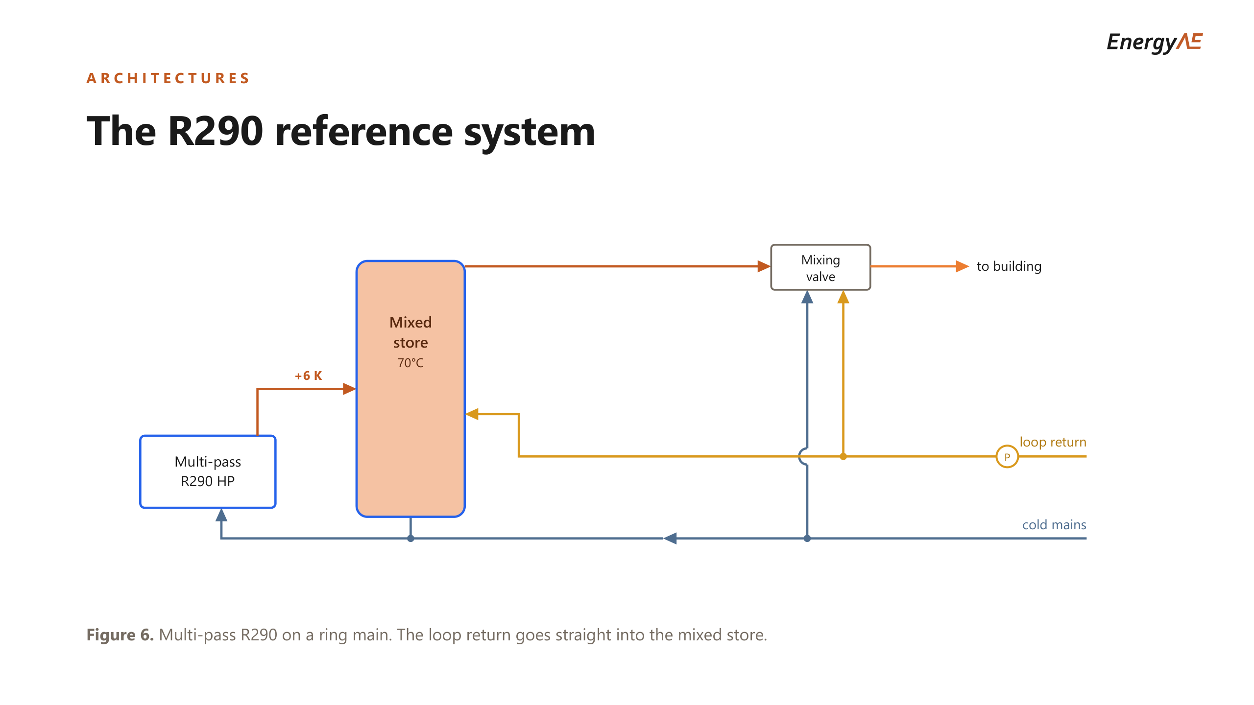
The R290 arrangement is the simpler one. The machine draws from a mixed store held at 70°C and lifts it about 6 K per pass, and the loop return goes straight back into that store. A store at 70°C being handed water at 55°C is unremarkable to a multi-pass machine, because it was drawing from a mixed store anyway.
The CO2 arrangement cannot do that, and the interactive slide below shows why. Option 1 is the cheap answer: put the loop return into the store. It fails, because 55°C water lands in the store the machine draws from, the cold end disappears, the inlet climbs past the 35°C cutout and the machine stops.
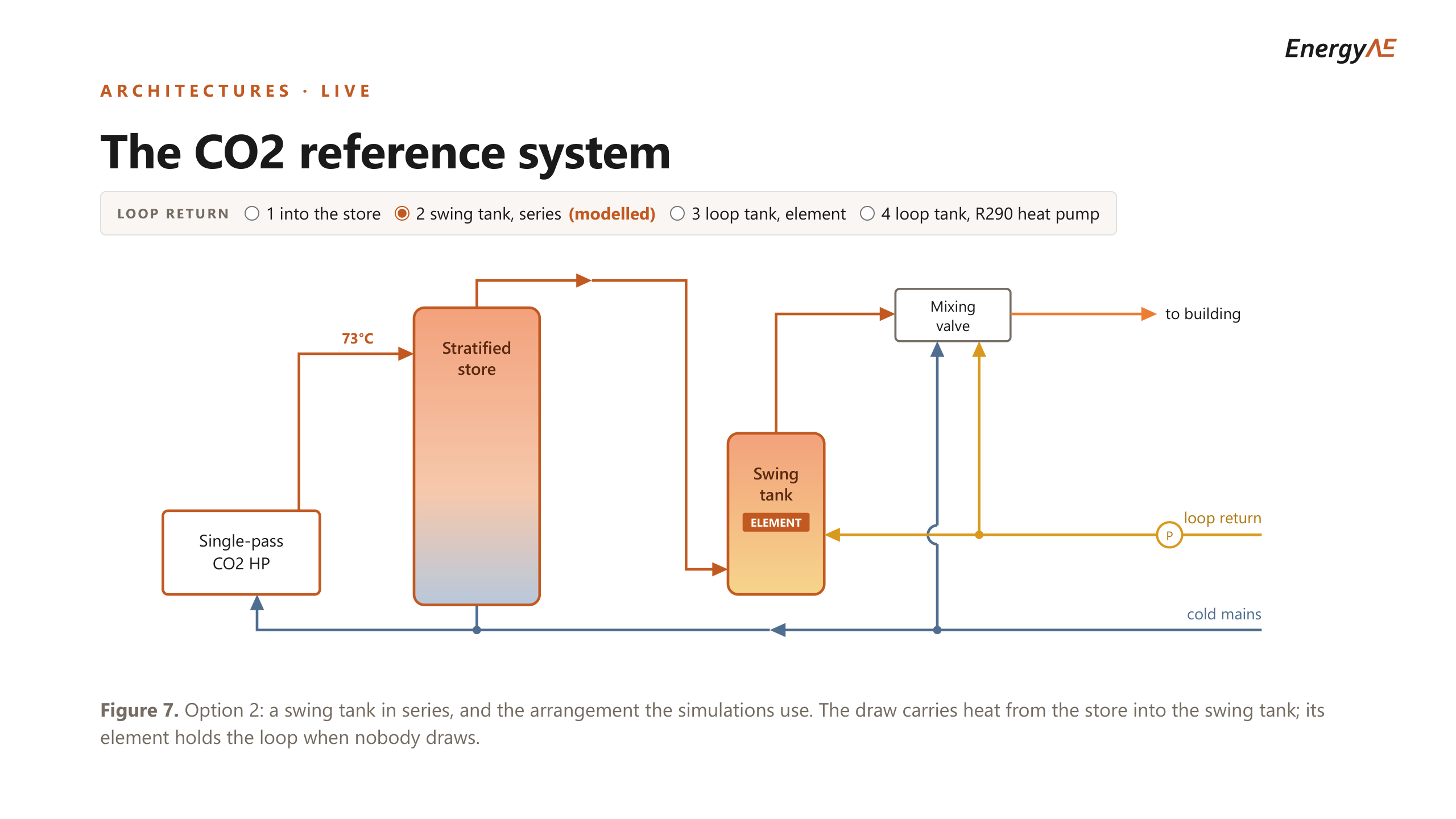
So the CO2 machine needs a finishing vessel to keep the return away from its store. Option 2, a swing tank in series, is what the simulations model. The store feeds the swing tank, the loop return goes into the swing tank, and the store never sees it.
Something then has to hold that swing tank at temperature when nobody is drawing, and the heat pump cannot, because reaching in would defeat the point of the tank. So it is an electric resistance element, running at a COP of 1.
Thermal energy modelling using TRNSYS software
Each system is simulated for a full 8,760 hours in TRNSYS at a 72-second timestep.
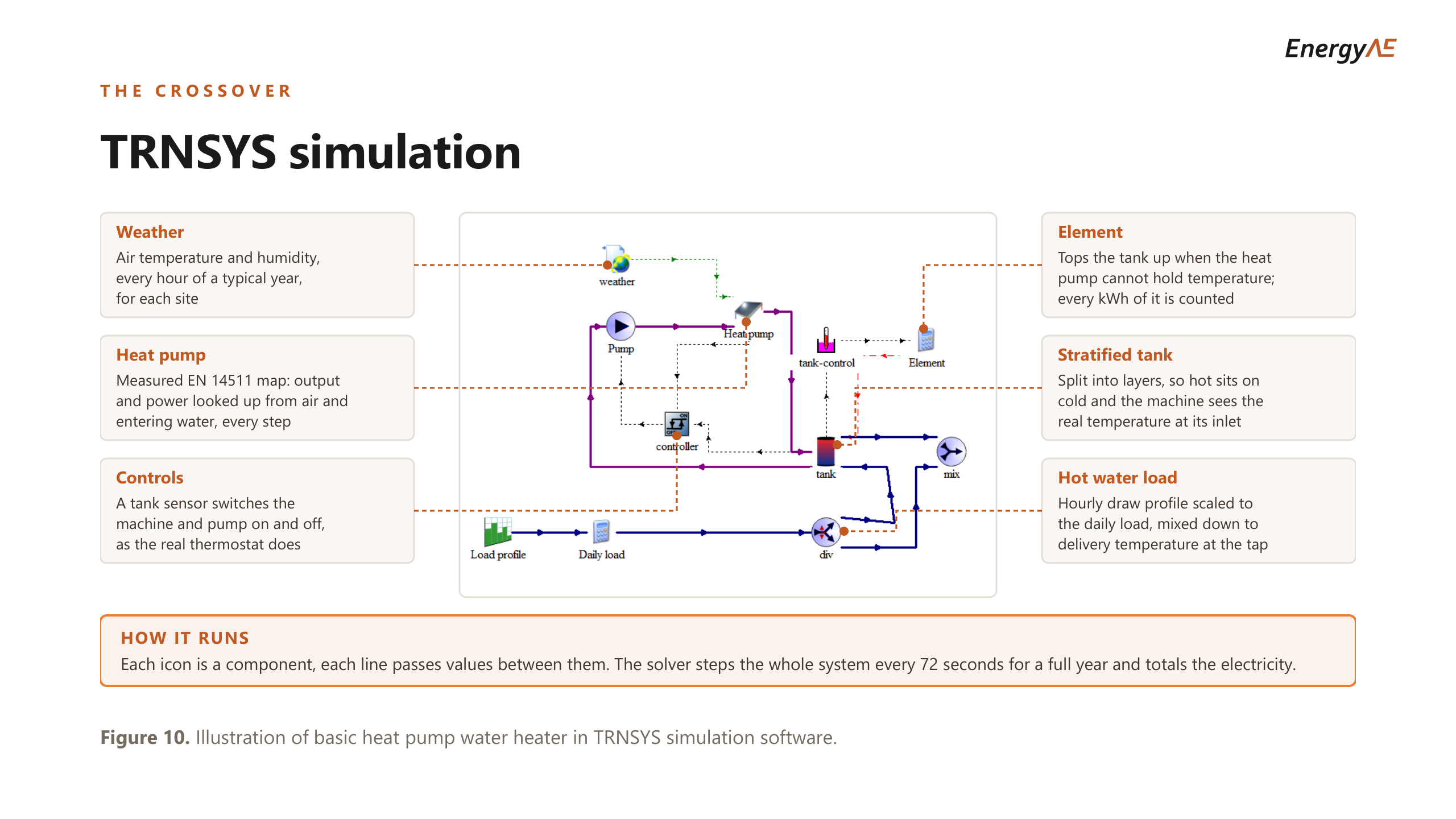
The heat pump is a lookup against its measured performance map at whatever air and entering water temperature it is seeing at that moment, rather than a rated COP. The tank is stratified, so hot sits on cold and the machine sees the real temperature at its inlet. Every kilowatt hour the resistance element contributes is counted.
For each case the plant was sized by search until it held every gate: the loop supply and return temperatures above, plus a 45°C delivery floor and an allowance of 1 percent of the year. The 45°C floor is EnergyAE’s own useful-delivery criterion and is not something AS/NZS 3500.4 asks for.
That gives 240 ring-main buildings that both machines can serve, across five climates from Dunedin to Sydney, daily loads from 250 to 4,500 MJ, and loop lengths to 600 m each way.
The cost comparison
The slide below runs the comparison live. Set the climate, the ring main length, the daily load and the shape of the day, and it reports the annual electricity for each system and the plant each one needs to get there.

Set the ring main to zero and the CO2 system wins every one of the 60 dead-leg cases, by about 15 percent. That is the cold make-up water condition, and it is what a transcritical machine is for.
Then lengthen the loop. At 150 m the CO2 system still wins 38 of 60 cases. At 300 m it wins 29, at 450 m it wins 16, and at 600 m it wins 15.
What is doing that is not the heat pumps. Once a loop is fitted, the CO2 heat pump holds a seasonal COP of about 3.1 at every loop length, because the loop never reaches its store. The R290 heat pump drops to about 2.7, because it is working on 65°C water.
So on heat pumps alone the CO2 system is ahead everywhere, and it still loses, because the swing tank element carries about 5 percent of the useful heat at 150 m, 14 percent at 300 m, 23 percent at 450 m and 30 percent at 600 m, all of it at a COP of 1.
The critical loss-to-load ratio
Loop length is not the right variable, because 300 m of loop means something different on a hospital than on a small apartment block. The variable that orders the result is the ring main’s daily heat loss divided by the hot water delivered in a day.

Below a ratio of 0.30 the CO2 system is cheaper by a median of 13 percent, and it wins 87 of those 88 buildings. Above 1.0 the R290 system is cheaper by 41 percent, and CO2 does not win one of the 84 buildings up there.
Between 0.30 and 0.40 the two are very close in performance. Anything landing in that band should be decided on capital cost, charge limits, plant room access and maintenance, and not on modelled running cost.
The pooled crossing is at 0.34, and colder mains water moves it right, in the direction the physics predicts. A transcritical machine’s whole advantage is the cold water it gets to work on, and there is more of that in Dunedin than in Sydney.
| Site | Mean cold mains | Crossover ratio |
|---|---|---|
| Dunedin | 10.9°C | 0.43 |
| Canberra | 12.1°C | 0.38 |
| Melbourne | 14.5°C | 0.32 |
| Auckland | 15.8°C | 0.33 |
| Sydney | 17.7°C | 0.26 |
Melbourne and Auckland land within 0.004 of each other on 1.3°C of mains temperature, which is the resolution of the method showing itself. The ordering holds at the ends and is noise in the middle, which is why the useful answer is a band of 0.30 to 0.40 rather than a number.
The mechanism underneath the whole curve is the element share. At a ratio of 0.07 the CO2 swing tank element carries almost none of the useful heat. At 0.44 it carries 14 percent, at 1.0 it carries 34 percent, and at 4.0 it carries 71 percent. The crossover is the point where the element that the CO2 machine’s inlet cutout forces on it starts to cost more than the cold-suction advantage that cutout exists to protect.
These figures would change with the building profile, the climate and the equipment chosen. Take the direction from this, not the precise ratios.
Applying it to a building
Start by working out the ratio, because you can get it off a drawing before any modelling. Estimate the loop’s daily standing loss from its length, bore and insulation, and divide it by the daily hot water demand.
Below about 0.30, a transcritical CO2 system on cold mains is a strong answer, and the colder the climate the stronger it gets. A dead-leg building is the clearest case of all.
Above about 0.40, the useful conclusion is not a refrigerant name. It is to get the loop off the resistance element. Give the ring main return its own tank and its own small heat pump, rather than a tank with an element in it, and the COP 1 term that drives the whole right-hand side of the chart goes away. That arrangement is option 4 on the CO2 slide above, it is close to what one of the New Zealand projects in the full deck actually built, and it is not simulated anywhere in this study. Choose the refrigerant after that decision, not before it.
Between 0.30 and 0.40, running cost does not separate them. Decide on capital cost, on whether you can site a flammable charge, and on who will service the plant.
And in all three cases, efficiency is one input among several. Capital cost, maintenance, refrigerant charge limits and plant room access decide as many of these jobs as annual electricity does.
If you need help with a commercial hot water project, get in touch.
The full presentation
The complete session is below, including the three New Zealand case studies and the sizing method that this article skips. Use the arrow keys to move through it, and F for full screen.
Find a recording of the presentation here.