Manufacturers preparing for heat pump water heater MEPS may be wondering: how do we make sure our product meets the 50°C delivery requirement in AS/NZS 5125.1 Appendix H?
The question has a false premise. There is no 50°C bar to clear. The 50°C delivery requirement is the mechanism that dictates which declared load size a product can be rated at.
A second belief is doing more damage: that control settings should be tuned to suit Appendix H to achieve 50°C, and that the settings used for MEPS and for AS/NZS 4234 scheme modelling must therefore be reconciled. These are two separate tests.
The 50°C threshold lives inside the AS/NZS 5125.1 Appendix H tapping cycle, and MEPS compliance is a laboratory test that 4234 modelling cannot demonstrate. We have, however, developed our own simulation using Python which replicates the Appendix H test, to give you insights. This Python simulation applies the same physics as TRNSYS.
This article sets out where the 50°C figure actually appears, what it decides, and what is left for a manufacturer to influence. The simulation results come from EnergyAE’s Python implementation of the Appendix H sequence, run across five representative products and 29 control configurations.
The two places 50°C appears
Twice, inside Appendix H, and inside the laboratory.
In Clause H.5.5, the maximum draw-off, hot water is withdrawn at 9 to 10 kg/min (the rate is set in H.4.4.3) until the outlet temperature falls to 50°C or until more than twice the tank volume has been drawn. That stage determines the maximum deliverable volume of water above 50°C.
In Clause H.6, the 24-hour tapping cycle, the unit must deliver a 24-hour thermal load across eight draw-off events with a minimum delivery temperature of 50°C at every one of them. The eight events all fall within the first 11 hours, at 0, 1, 4, 6, 8, 9, 10 and 11 hours, following the same daily load profile shape as AS/NZS 4234 Table A.6.2.
It appears nowhere in AS/NZS 4234. That standard sets a minimum delivery temperature of 45°C in Clause 3.6.3, and that is still the figure for every scheme submission to CER, VEU and ESS. Until a scheme changes its own rules, 45°C is the number that applies to 4234 modelling.
The two are not a 45-to-50 rule change, and treating them that way is the root of the confusion. They are different tests, on different timescales, measuring different things.
| AS/NZS 4234 | AS/NZS 5125.1 Appendix H | |
|---|---|---|
| What it is | An annual simulation, 8,760 hours | Maximum delivery volume, re-heat + 24-hour laboratory test, per ambient condition |
| Used for | STC, VEEC and ESC certificate claims | GEMS MEPS compliance and declared values |
| Minimum delivery temperature | 45°C (Cl 3.6.3) | 50°C (H.5.1, H.6.1) |
| Load | Peak daily load scaled by a seasonal multiplier | A fixed 24-hour load, one ofnine declared sizes |
| Control settings | The product’s own declared default | Mandated by H.3.4 - 60°C or as close to as possible |
| Output | Annual energy savings | Maximum delivery volume, re-heat time, 24-hour cycle COP |
The tapping profile is the same shape in both. Even the step-down logic is shared: 4234 Clause 3.6.3 NOTE 2 allows a system that fails 45°C to be rated at a lower load that satisfies it, which is exactly what Appendix H does with its nine load sizes.
Interactive MEPS test
Appendix H is a series of draw-offs run back to back, and most of the trouble with the 50°C figure comes from conflating it with the 45°C minimum delivery temperature in AS/NZS 4234.
The simulator below runs the whole sequence on a real 216, 266 or 316 litre product: fill the tank with cold water and heat it, run the pre-conditioning draw-offs, draw it down until the outlet reaches 50°C, recharge it, then run the 24-hour tapping cycle. Press play and the whole test, two days of it, is simulated in about twenty seconds, with the tank stratification on the left and every sensor on the chart.
Click a stage band to zoom into it. That is the only way to watch the maximum draw-off, which decides V50 and takes about twenty minutes out of the whole test.
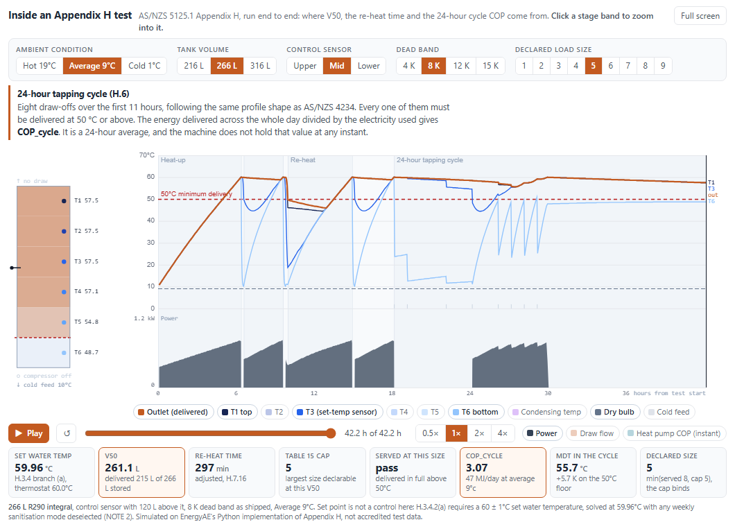
Every number in it is simulated, and taken at the set point H.3.4 requires rather than the one the product ships with.
Deliverable volume and the declared load size
Appendix H Table H.6.1 defines nine declared load sizes, from 9.4 MJ to 85 MJ per day. In contrast, a small and medium (most typical) load in 4234 is around 25 and 42 MJ per day.
The test procedure in H.6.3.5 searches for the size a product can serve, and the search runs in both directions. A size is too large if the outlet falls below 50°C at any draw, or if the thermostat does not cut out (stop heating) within the 24 hours. A size is too small if the thermostat never cuts in (starts heating) at all, or if the final cut-out happens before the last tapping event.
That second direction may surprise people - the smallest load is not a free pass. A 300 L tank handed a 9.4 MJ day is never challenged, the test reports the load as too small, and the laboratory must repeat the cycle at a larger size.
Then a second constraint arrives from a different document. The GEMS Heat Pump Water Heaters Determination 2026, currently an exposure draft, caps the load size a product may declare according to its V50, the maximum hot water volume from equation H.7.2. Under 100 L allows size 1 only; each further 50 L band adds one size; 450 L or more allows the full range.
So the declared size is the smaller of two separate things:
- the largest size the unit can serve, from the 24-hour tapping cycle; and
- the Table 15 cap, from the maximum draw-off.
A note on V50: it is not the volume delivered, and it is not the tank volume. It is a 50°C-equivalent volume, the integral of mass flow weighted by how far the delivered water sits above the cold inlet relative to a 50°C reference. Think of it as total volume tempered to 50°C. It exceeds the delivered volume whenever the water is hotter than 50°C. In this study the integral units returned a V50 of 0.90 to 0.98 times tank volume, while the CO2 split returned 1.21 times its tank volume, because the compressor keeps contributing throughout the long draw-off.
How control settings and tank geometry impact the declared size
The maximum draw-off begins within 10 minutes of a pre-conditioning reheat that runs to thermostat cut-out. The dead band sets the cut-in. As a result, the draw-off always starts from a fully charged tank, whatever the dead band is, and V50 barely moves.
The 24-hour cycle is different. A wider dead band means the unit waits longer before restarting, the tank temperature drops further between draw-offs, and the later draw-offs are delivered closer to the 50°C floor.
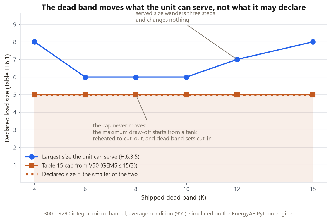
Across all the simulations we tested, the Table 15 cap was the binding constraint, the one that set the declared size, every time. V50 varied by less than 2% across each dead-band sweep, and the cap never changed. The size the unit could serve wandered by three or four steps and changed nothing.
The simulations behind the player above cover a wider grid, 108 configurations of tank volume, sensor position and dead band across all three ambient conditions, and the cap held constant in every one of the nine volume-and-condition groups. What changes is how often the cap is the constraint that sets the declared size. At the hot and average conditions it was in 30 of 36 each. At the cold condition the unit serves a smaller load, and the split is even: the cap set the size in 17 of 36, the 24-hour cycle in 17, and both in 2. A product sized tightly enough to rely on its cap at 9°C may find the 24-hour cycle setting its size at 1°C instead.
For a manufacturer that inverts the usual advice. The dead band is not the lever on your declared load size, and therefore not on your MEPS COP. Tank volume, geometry and sensor position are, because they influence V50.
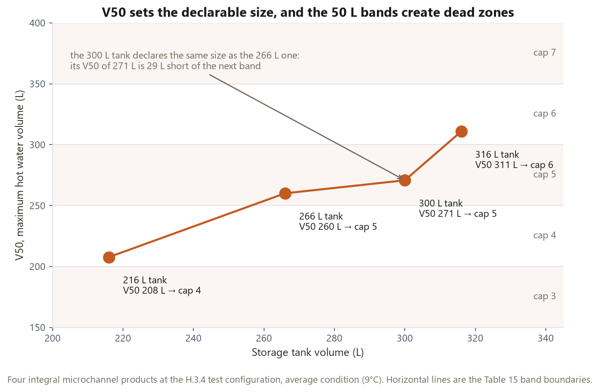
The banding creates dead zones worth checking before a tank size is locked in. In this group the 300 L product reaches a V50 of 270 L and lands in the same band as the 266 L product, so the extra 34 L of storage buys nothing at all. It needs a V50 of 300 L to move up a step.
COP against declared load size
COP rises steeply with load size at the small end of the range. On this product the cycle COP runs 2.24 at load size 1 and 3.15 at size 5. That is the difference between a marginal rating and a comfortable one, decided entirely by which size the product may declare.
It also puts the MEPS level in perspective. The exposure draft sets the bar at a COP of 2.0 at the average 9°C condition, which the guidance confirms is intended to sit around 60% annual energy savings in zone 3. Almost nothing will fail that, once a sensible load size is declared. The qualifier matters: across 16 stand-alone systems we simulated separately, none reached COP 2.0 at a 9.4 MJ load, 12 of 16 did at 19 MJ, and all 16 did at 28 MJ. Products do not fail MEPS on efficiency. They fail it, if at all, by being rated at the wrong load size.
One edge case is worth knowing about. In four of the 29 configurations, the size at the Table 15 cap was one the 24-hour test reported as too small to challenge the unit. A strict reading sends the lab to a larger size, and the cap forbids it. The cap and the test method can disagree, and a product sitting on that boundary should expect questions.
The control settings Appendix H tests
You do not choose the set point for this test. Clause H.3.4.1 requires that where the set water temperature can be adjusted, the heater is set to an operating mode that achieves a consistent set temperature and adjusted to a set temperature at or closest to 60°C. H.3.4.2(a) makes it a hard requirement: where a consistent 60 ± 1°C can be achieved, the mode or the thermostat cut-out shall be adjusted to achieve it.
“Set water temperature” means the temperature at sensor 3 out of 6, which has 41% volume above it.
The GEMS determination section 15(1)(b) requires an operating mode and control settings that an end user could actually use. And Appendix H H.3.1 prohibits circumvention devices outright - that covers software that alters behaviour during a test.
Legionella cycles
There is also a clause that catches people out. H.3.4.1 NOTE 2 says a product should not be tested in a weekly high-temperature Legionella mode where a steadier mode is available, because those modes do not hold a consistent set temperature. In our modelling this mattered more than expected: with the weekly cycle active, the heat-up reached 61.1°C regardless of what the thermostat was set to, because the sanitisation target overrode the thermostat set point. With the weekly cycle deselected, the measured set water temperature matched the thermostat setting exactly.
Consistency between MEPS & 4234?
MEPS and scheme modelling run on different control configurations, and they are not required to match. Appendix H mandates its own set point.
Scheme (4234) modelling runs the product’s declared default: regulators all require modelling on the system’s default setting, consistent across the test report, control declaration and user manual.
H.3.4.1 NOTE 3 warns that using a 60°C set water temperature may significantly overestimate the heated water delivery of a product that routinely heats to a lower temperature, such as one using a weekly sanitisation strategy. The standard knows it is testing a configuration that is not how the product runs in a house.
Summary
To sum things up:
- Appendix H specifies the set point for testing and it does not need to align with your factory defaults
- The 50°C minimum delivery temperature applies only to defining the maximum delivery volume (V50), and the load size for the 24-hour COP test, which is itself capped by GEMS limits based on you V50
If you would like your own product run through this before testing, our MEPS simulation service does exactly that, and we are happy to talk it through.