Tank Model Parameters
How to enter tank parameters in the Commercial TRNSYS Tool.
Tank parameters tell the TRNSYS model how the physical tank is configured: its volume, insulation, fitting heights, and heat exchanger geometry. These feed directly into the stratification model and heat loss calculation, so accuracy here is important.
Where to Find the Parameters
All tank parameters come from the tank drawing provided by the client. The drawing must include a data table showing:
- Total internal volume (litres)
- Heights above the tank base for all inlets, outlets, elements, and temperature sensors
- If the tank has an internal coil HX: coil dimensions (height, inner/outer diameter, number of turns or length)
- Insulation thickness and material (used for the Appendix E heat loss calculation if tank >700L)
- Wall thickness and material
If the tank drawing does not include a data table, or if dimensions are missing, request an updated drawing from the client before proceeding.
Entering Parameters in the TRNSYS Tool
Step 1: Navigate to the Tanks sheet in the Commercial TRNSYS Tool.
.png)
Step 2: Add each tank model name to the first row of the table.
.png)
Tank model names
Step 3: For each tank model, enter all parameters from the tank drawing. Add screenshots of the drawing alongside your entries so the reviewer can verify values against the source document.
Key parameters to enter:
| Parameter | Source | Notes |
|---|---|---|
| Tank volume (L) | Tank drawing | Internal volume, not nominal |
| Tank height (mm) | Tank drawing | Used to derive node heights |
| Height of HP inlet/outlet | Tank drawing | Measured from base |
| Height of cold water inlet | Tank drawing | Measured from base |
| Height of hot water outlet | Tank drawing | Measured from base |
| Height of element (if fitted) | Tank drawing | Measured from base |
| Height of temperature sensors | Tank drawing | All sensor locations |
| Coil HX height (if applicable) | Tank drawing | Bottom and top of coil |
| Tank heat loss (W/K or kWh/24h) | 4692 report or App E | See Tank Heat Loss Calculation |
.png)
Example tank drawing with data table
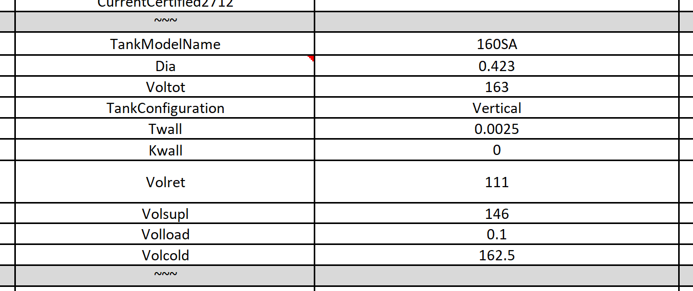
.png)
Corresponding entries in TRNSYS Tool Tanks sheet
Step 4: Select the tank model for each heat pump system in the FAM_COM sheet. Once selected, the tank parameters will populate automatically from the Tanks sheet.
Sanity Checks
Before moving on, verify:
- The sum of volumes at each node height looks consistent with the total tank volume.
- HP inlet and outlet heights make physical sense for the system (e.g. HP return is at the bottom, HP outlet is at the top).
- If the tank has multiple inlets for a gas booster or second heat source, confirm all are represented.
- For systems with multiple tanks of the same model, confirm the number of tanks is set correctly in FAM_COM — the total system volume affects the CPL calculation.
For tanks greater than 700L, the heat loss value is calculated using the AS/NZS 4234:2021 Appendix E spreadsheet rather than a physical test report. See Tank Heat Loss Calculation for the process.